hadow.fr
 openPGP public key
 Matrix.org
 Gitea
Gitea- GitHub
sam(dot)hadow(at)proton(dot)me
prefer Matrix if you want to use E2EE
@fire:hadow.fr
main git
3d Printed And Handwired 60% Keyboard
by Sam Hadow
I’ll describe in this short blog post how I 3d printed (not including the keycaps this time) a 60% keyboard (61 keys). Then hanwired it, and installed a firmware with ZMK on it. It is similar to the numpad, just a bigger project. Read the numpad post first if you want more detailed instructions on how to handwire a keyboard.
steps
3d printing parts
Just like for the numpad I designed the parts with openscad, the parts and bash scripts are in the same repository here.
The script keyboard60.sh can be used to generate the stl files for the backplate and case. They’re both cut in half to make them fit on my 3d printer plate.
If you want to 3d print the keycaps, there is a script too. But I personally used keycaps I already had on the side instead, mostly to see the letters better on the keycaps. The side engraving on my 3d printed keycaps is not that visible.
I printed the parts with my bambulab P1S 3d printer, I used a 0.4mm nozzle and a 0.16mm layer height, white PETG filament as the material.
I used T8000 glue to glue the parts.
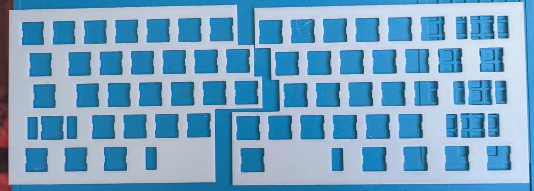
The backplate looks like this before gluing the two halves:
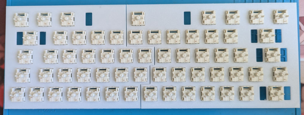
With the switches mounted (I used MMD holy panda switches this time too):
handwiring the keyboard
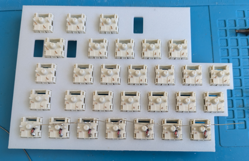
Just like with the numpad we first need to bend the diodes so that it’s easier to solder them to the switches. I then soldered the rows with the legs of the diodes and cut the extra length after the anode.
The keyboard is handwired columns to rows, so the diodes are soldered with the anodes soldered to the switches pins (the red part here). I used 1N4148 diodes as they’re very cheap.
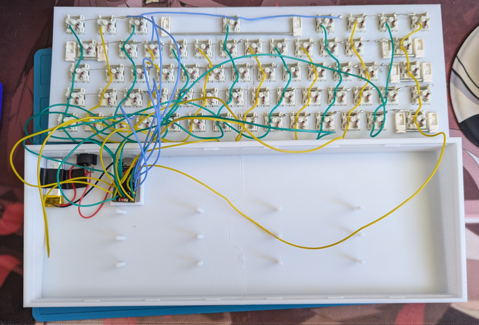
And then after a few hours of soldering, and gluing the two haves together:
(I also mounted the stabilizers, this time I used cheap plated mounted stabilizers.)
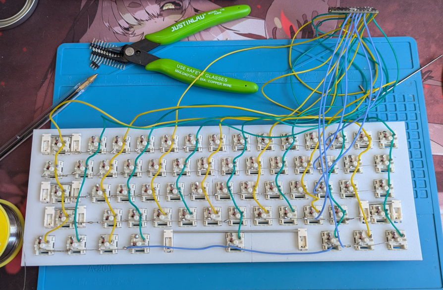
I used yellow and green wires alternating them between the columns to have an easier time soldering them to the microcontroller and writing the firmware after. I also used a pen to mark where to strip the wire to solder it to the pins. It was more convenient than just using my thumb to hold the wire where I have to strip it.
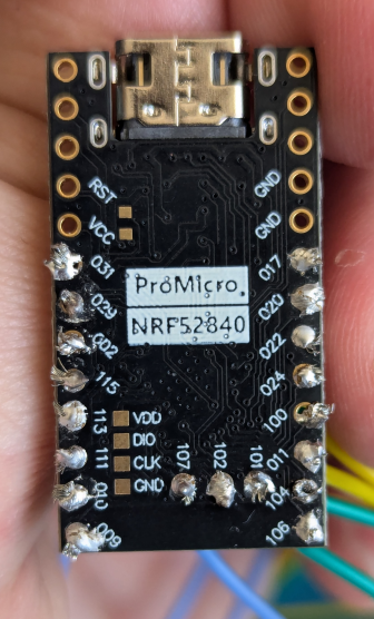
And this time too I used a Pro Micro NRF52840.
flashing the firmware
I used ZMK to flash the firmware, you can find the ZMK configuration in this repository and this one for github action to automate the build process. This keyboard is named keeb60_3d. Like in the previous blog post, I recommand flashing the firmware before clipping the backplate in the case as you might have to reset the microcontroller to flash a fixed firmware.
assembling the keyboard
I glued the two halves of the keyboard, taped the battery on the side of the case, soldered it to the microcontroller and the power switch of the keyboard.
Like last time the switch is a 15mm round switch like this one. And the battery is a 3.7V LiPo battery with a 320mAh capacity (for the bluetooth).
I then glued the microcontroller in its holder, clipped in the backplate to the holder and mounted the keycaps.
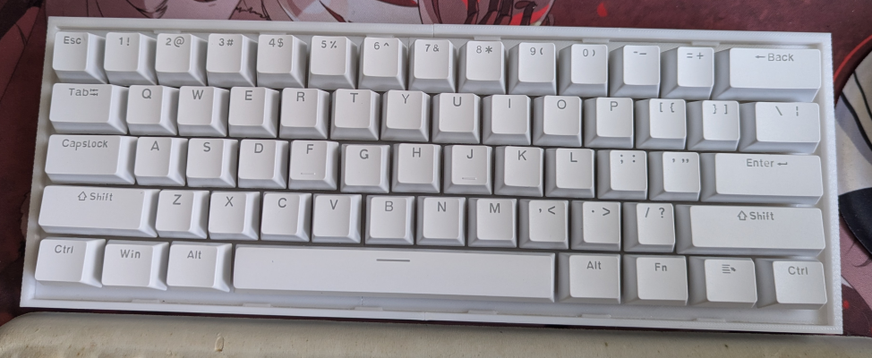
final result
The keyboard:
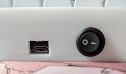
The power switch and USB C port in the back:
Copyright (c) March 2026 Sam Hadow Verbatim copying and redistribution of this entire page are permitted provided this notice is preserved.