hadow.fr
 openPGP public key
 Matrix.org
 Gitea
Gitea- GitHub
sam(dot)hadow(at)proton(dot)me
prefer Matrix if you want to use E2EE
@fire:hadow.fr
main git
3d Printed And Handwired Numpad
by Sam Hadow
In this blog post I’ll describe how I (mostly) 3d printed a numpad (21 keys keyboard), hanwired it, and installed a firmware with ZMK on it.
steps
3d printing parts
I designed the parts with openscad, the repository is available here.
I used the script keycaps_numpad.sh and the openscad script xda_keycap.scad to generate the stl files for the keycaps with an engraving on the side for each keycap. Then generated the stl files for the backplate and case with the files backplate_numpad.scad and case_numpad.scad.
I then printed them with my bambulab P1S 3d printer, I used a 0.4mm nozzle and a 0.08mm layer height. I used white PETG filament to print all the parts. All the parts took about 12 hours to print.
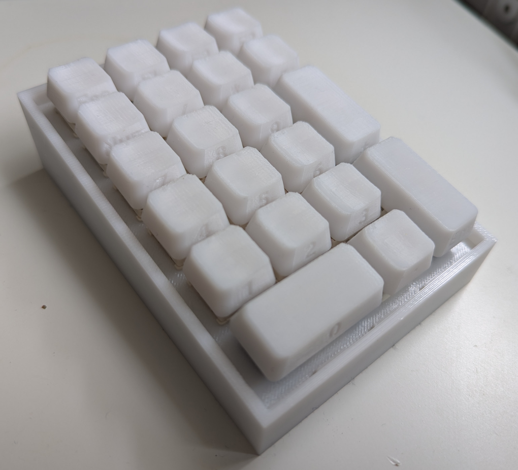
Here is the result for the 3d printed parts:
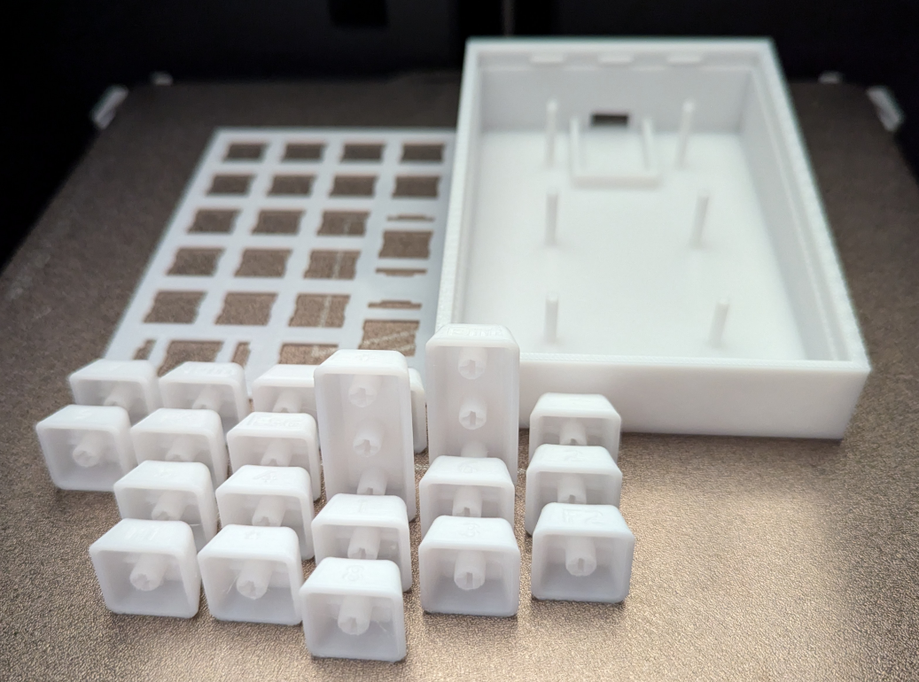
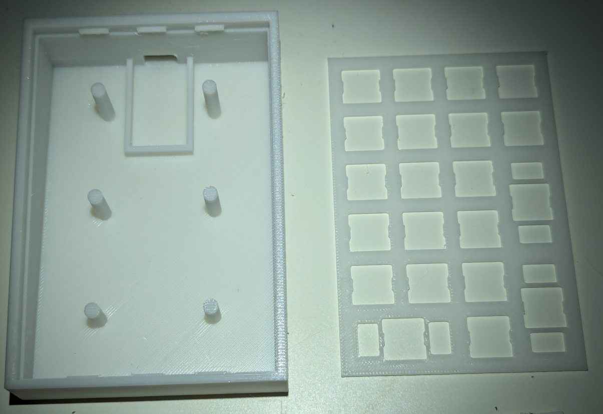
You’ll notice the backplate and the case changed between the two pictures. I changed the backplate design to be able to fit stabilizers instead of printing them myself. And for the case I changed the design to have stronger pillars and also enabled supports generation in the slicer.
You’ll also notice the keycaps were printed with the side, and not the bottom, facing the plate. It takes longer to print but gives a smoother top with a XDA keycap profile. The engraving was printed facing away from the plate to make the seam between the front and top of the key smoother.
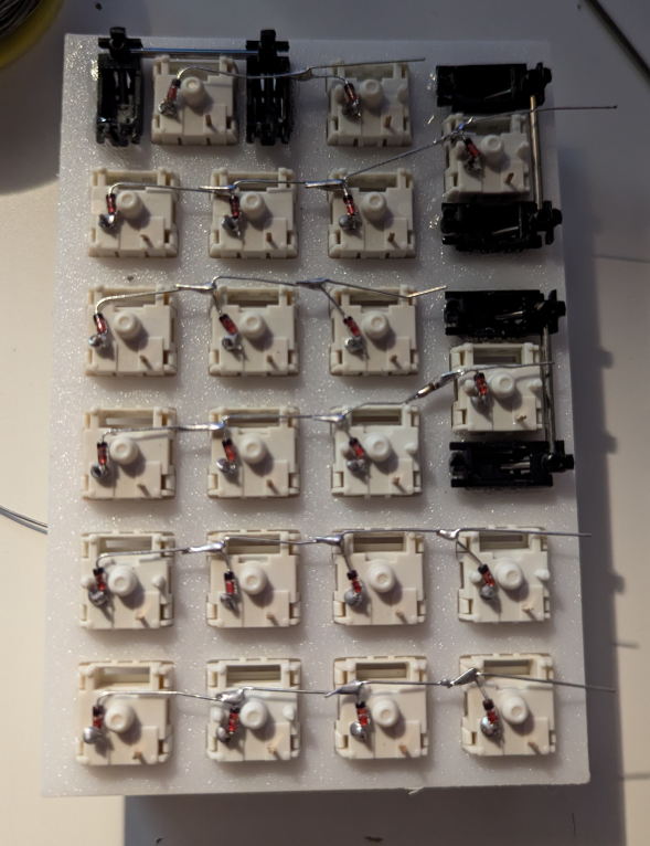
mounting the switches and stabilizers on the backplate
I used MMD holy panda switches and cheap plate mounted stabilizers that I glued on the backplate. Just be careful not to glue the metal part to the stabilizer and pay attention to the orientation of the metal parts so that they don’t collide with the pillars in the case.
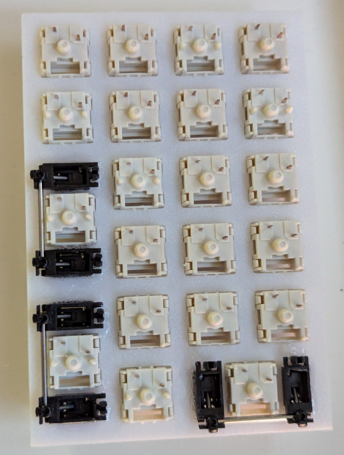
You’ll notice some switches have 2 additional legs, they’re the same switches apart from this variation which doesn’t matter in this build. These two additional plastic legs are for PCB mount builds but are still adequate for plate mount builds. Just buy the cheapest version, or the one in stock with your supplier.
handwiring the keyboard
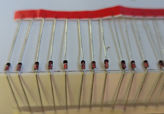
bending the diodes
The diodes are just there to have the current flowing in one direction (in my build from the columns to the rows) so you can use whichever diodes you have. I used 1N4148 diodes myself as they’re very cheap.
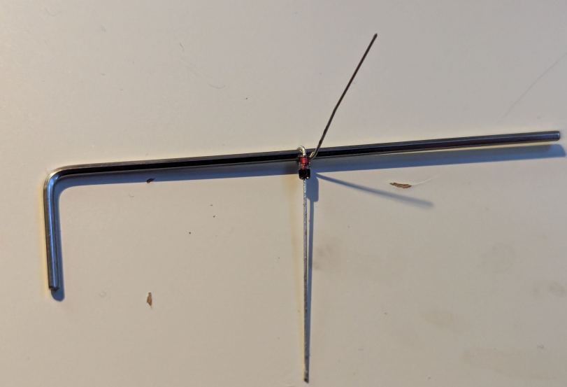
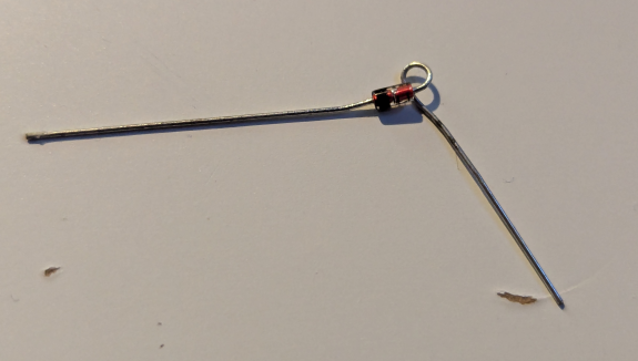
We first need to bend the diode to have an easier time soldering them to the switches pins, I used the edge of my desk and then a small L shaped hex key to bend the diodes. For this build we need to prepare 21 diodes.
Pay attention to the orientation of the diode, the anode (red part here) needs to be where the bend is while we keep the wire after the cathode (black part) straight
soldering the diodes
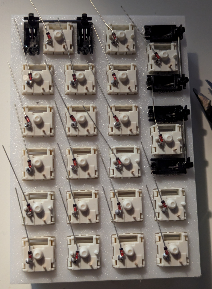
We then need to solder the diodes to one pin for each switch, you can pick the “top” or “bottom” pin, it doesn’t matter as long as you’re consistent with your rows and columns wiring later. You can stay consistent and always pick the same pin to have an easier time wiring the rows and columns but electrically it doesn’t matter. After soldering the diodes you can cut the extra wire after the anode.
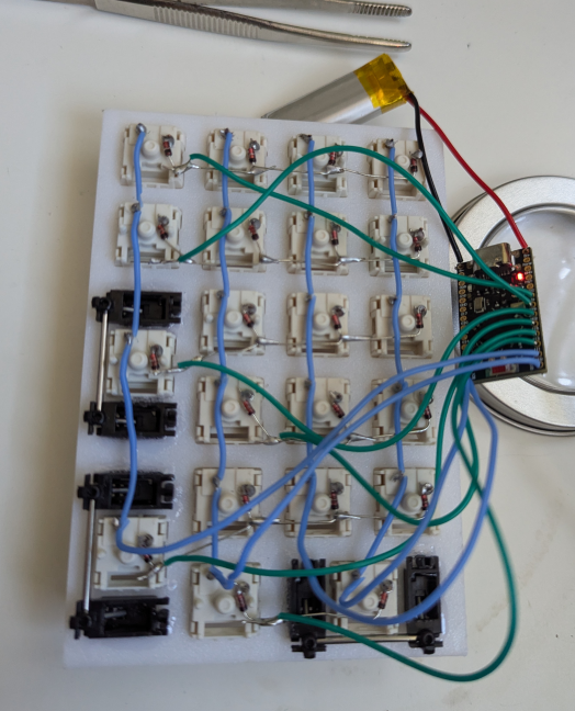
wiring the rows
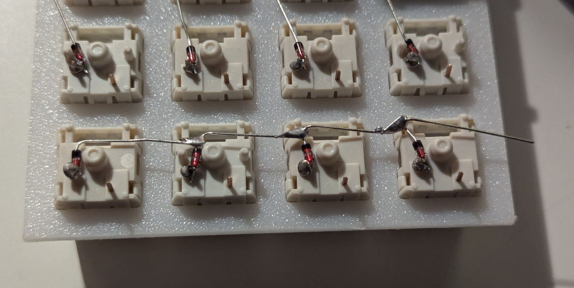
I used the extra wire after the cathode on the diodes to wire the rows like this:
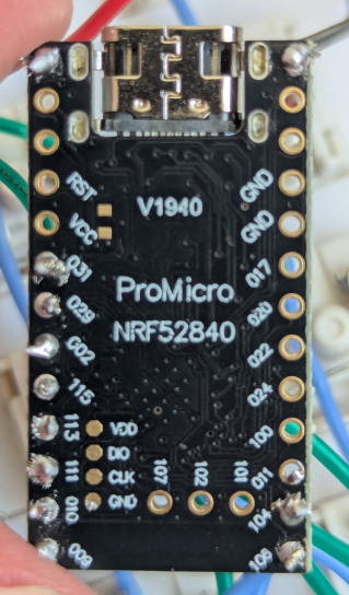
wiring the columns and the microcontroller
After wiring the rows, wire the columns using the other pin on each switch. And then wire each row and column to a pin on your microcontroller. I used a pro micro nRF52840 as it support bluetooth, is supported by ZMK, and is pretty cheap. I also wired a 3.7V LiPo battery with a 320mAh capacity to the controller to be able to use the keyboard wirelessly. The capacity doesn’t matter much, above 300mAh is good to have a long lasting battery. At least if you don’t plan to use RGB leds.
Also note to which pin you wire each row and column to adapt the ZMK layout later.
flashing the firmware
I recommend flashing the firmware before clipping the plate in the case so that you can easily access to reset pin to reset your microcontroller if you mess up the firmware and proceed with trial and error with ZMK.
I have this repository and this one on github as the build process is simplified with github action. The config for this keyboard is in zmk-config/boards/shield/numpad3d, in there you need to define the layout in numpad3d.keymap and the GPIO mapping for each row and column in numpad3d.overlay. You can also enable the bluetooth and tweak some features in numpad3d.conf. You then need to specify the keyboard to build and which microcontroller is used in zmk-config/build.yaml.
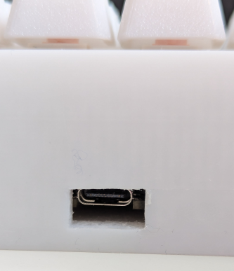
To flash the firmware you plug in the microcontroller and copy the firmware to the detected disk device, the microcontroller will then automatically reset itself.
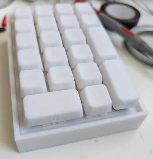
assembling the keyboard
You can then assemble the keyboard. I used electrical tape to keep the microcontroller and the battery in place in the case. After that I clipped in the plate in the case and added the keycaps on the switches. Here is the final result:
possible improvements
Overall 3d printing and handwiring this keyboard was a fun project but, as always, there are possible improvements, I’ll list them here in no particular order.
- Adapting the github action automation to gitea action.
- Designing a screw in cover to hold the microcontroller and battery in place instead of using electrical tape.
- Multi filament printing and having a text in a different color instead of an engraving for the keycaps, though I don’t own an AMS yet. Currently the keycaps look okay during the day, but it’s harder to see the engraving in low light conditions.
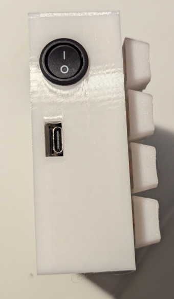
Adding a switch on one of the battery wire to be able to turn off the keyboard. Currently it’s constantly on.
Update 24/03/2026
I modified the case a little and added a switch for the battery to turn off the keyboard. The switch I used is a 15mm round switch like this one (sanitized and non affiliated link).
Copyright (c) March 2026 Sam Hadow Verbatim copying and redistribution of this entire page are permitted provided this notice is preserved.